
GENSIM Test Set
GENERATOR SIMULATOR FOR EXCITATION SYSTEM TESTING
A microprocessor-based Excitation System test set intended for use on all modern excitation systems & voltage regulators, both analog and digital.
The GENSIM® test set is designed for set-up calibration, maintenance testing, and troubleshooting. This equipment will simulate generator and exciter operation to safely perform a complete test of the excitation system & voltage regulator and related protective devices, while the Turbine-Generator is shut down.
Set up your Excitation Systems to provide the maximum amount of VARS that the Generator can safely provide to support the power system needs and interconnection requirements.
Comply with NERC and WECC excitation system voltage regulator reliability standards requirements.
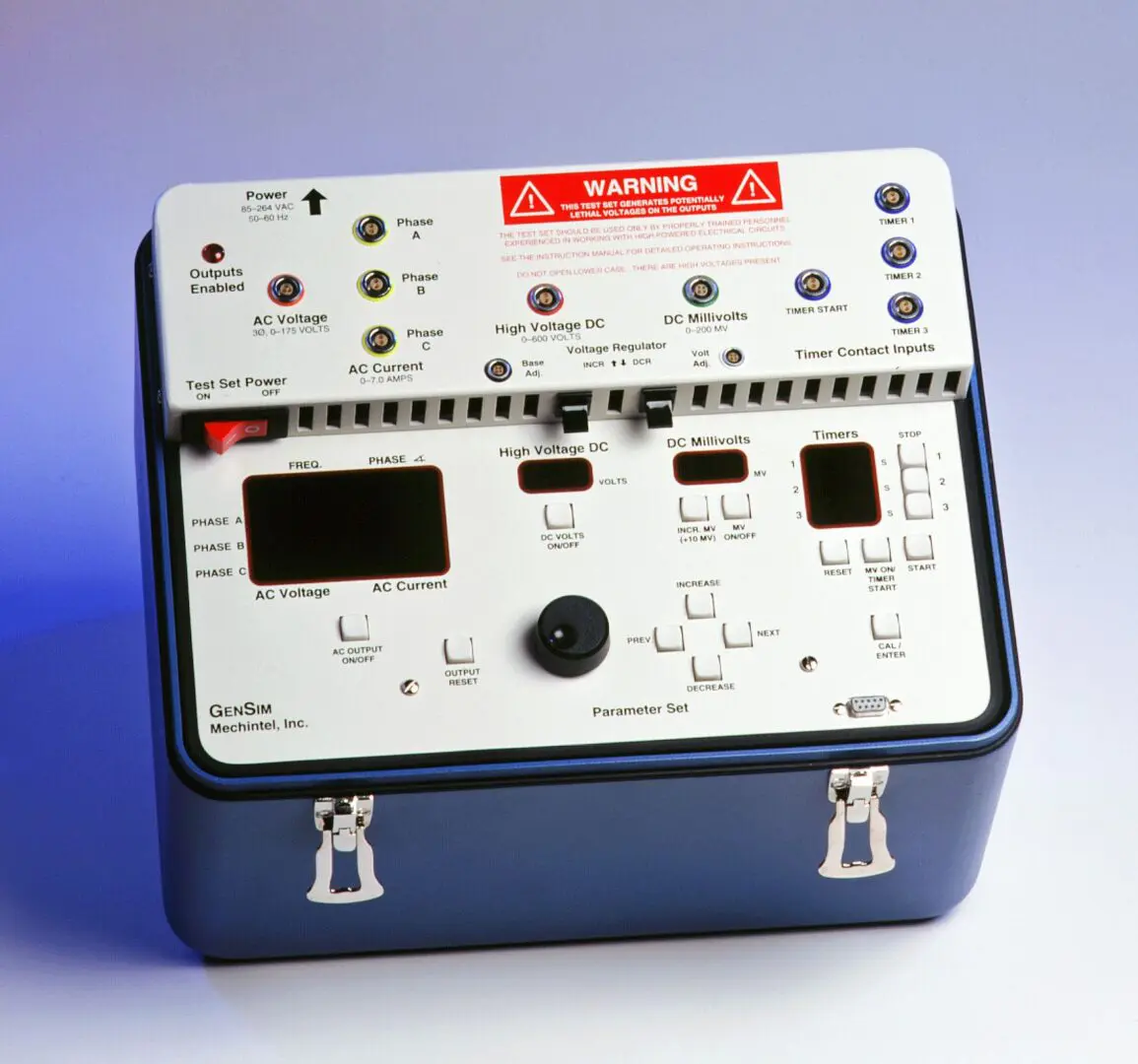

All components are contained within one portable case, 13" tall 15" wide 11.5" deep, weighing approximately 40 pounds
APPLICATIONS:

FEATURES:
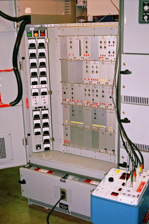
GenSim in operation
GenSim with WTA Brushless
GenSim with Alterrex System
OPERATION
WARNING:This instrument can produce voltages that may be harmful or lethal when contacted by the user. These voltages are part of the necessary functions of the instrument.
Only properly trained personnel experienced in working with high voltage electrical circuits should use the instrument.
Always turn the instrument off when connecting or disconnecting high voltage circuits.
General operating points:
When the power switch is turned on, the set boots up with the processor running and all the outputs off.
An OUTPUTS ENABLED indicator on, the top left side of the connector panel, is illuminated when one or more of the outputs are turned on. The parameter value displays are also brighter, and the display arrow points upward when an output is enabled and turned on. Conversely, the displays are dim and the display arrow points to the right when the parameter is off.
The various outputs can be switched off and on using their respective ON/OFF push buttons.
Any parameter to be adjusted can be selected by pushing the PREV PAR or NEXT PAR buttons to the right of the control knob. If the output for the selected parameter is OFF, turning the control knob or pressing the INCREASE & DECREASE push buttons adjusts the preset value of the parameter, but the output remains off. When the parameter is turned ON, the output value will go to this preset value. When adjustments are made with the output ON, the output values (and the preset values) are changed directly and immediately.
When an output is turned on using the ON/OFF button, the display for that parameter will brighten and the display arrow will now point up toward the output connections.
The selected output parameter can then be adjusted using either the control knob or the INCREASE & DECREASE push buttons. Typically, the control knob is the course adjustment, and the push buttons are the fine adjustment.
The OUTPUT RESET button returns all output values to zero, and the frequency set point is preset for 60 Hz.
The reset button on the timer section will reset the timers to zero seconds.
Timers can be started and stopped using either the push buttons or external (wet or dry) contacts, in any combination. The contact sensing circuits are designed to withstand voltages as high as 250 volts DC. If no voltage is present on either side of a contact, the contact sensing circuit will apply about 14 volts to the circuit for use in sensing the contact state change.
The maximum output values, of the various parameters, are software controlled for protection against overload.
Using the simulated generator PT volts and CT amps:
This feature will typically be used for checkout and calibration of the voltage error detector, the minimum excitation limiter (MEL or URAL), reactive compensation devices and the volt per hertz limiting and protective devices.
Select AC VOLTAGE by using the PREV PAR or NEXT PAR buttons to move the arrow next to the B PHASE voltage display.
Push AC OUTPUT ON/OFF push-button and observe the display brighten up. Adjust the output voltage to the desired value using either the knob or the INCREASE & DECREASE push buttons.
After output voltage is adjusted to the desired level, the current parameter can be selected and the output current increased to the desired value. With the current parameter selected, the output of the current level can be raised or lowered in 0.1-amp increments using the knob. The INCREASE & DECREASE buttons will change the output 0.01 amps per depression.
After the minimum required current output of 0.25 amps is obtained, the phase angle display will indicate the phase angle relation between the voltage and current.
The phase angle can then be selected and controlled to the desired values. The phase angle display will indicate 0 degrees at simulated unity power factor, positive degrees in the overexcited (vars out) region and negative degrees in the under-excited (vars in) region. At zero power factor, under-excited, the display will indicate minus 90 degrees.
Checkout and setting of the volts per hertz devices can be accomplished by adjusting the voltage and/or frequency of the 3-phase voltage output.
If desired, the AC OUTPUT can be switched off using the ON/OFF push-button. When this button is used, and the processor remains on, the set point is remembered so when the output is turned back on the voltage, frequency, current and phase angle return to the previous settings.

Using the millivolt source to simulate a current shunt
The millivolt (mV) source will typically be used to simulate the output of a current shunt. With the wires to the shunt lifted, the GenSim leads will be connected to the wires or to some other convenient point within the excitation equipment.
The mV source is designed with external voltage sensing at the end of the supplied test lead so that precise mV readings will be obtained. For this reason, the mV test lead (green stripe) needs to be plugged in for the millivolts to be displayed on the GenSim.
With the millivolt parameter selected, the output on the mV level can be raised or lowered in 1.0 mV increments using the knob. The INCREASE & DECREASE push buttons will change the output 0.1 mV per depression.
If it is desired to run an input-output calibration curve on the transducers, then the 10-mV stepping function can be used by briefly holding down the INCR MV (+10 MV) button. After the auto-steeping is enabled, the mV output will start to automatically increase in 10 mV steps at 10 second intervals.

Using the three event timers
The three event timers are very versatile and can be used several different ways. All three timers will start when the START button is pushed or when a contact state change occurs if you connect a contact to the TIMER START input. The three timers will also start when the MV ON/TIMER START button is pushed. When using the mV on/timer start function, you should preset the desired mV value. Having the ability to simultaneously start the timers with the MV output coming on is convenient when testing the field overcurrent devices that are calibrated to a millivolt verses time curve.
The timers can be stopped by pushing the individual STOP buttons or by hooking up one, two or three of the contact sensing inputs. The contact sensing can be hooked to any circuit with a voltage level within the range of zero to 250 volts DC. When the contact sensing function detects a change in state, that individual timer will stop.
The TIMER RESET button resets all three timers to zero.
By using the contact sensing feature, a more precise time delay calibration may be obtained.
Using the high voltage DC to simulate exciter output
The high voltage DC will usually be used to calibrate a field voltage sensing device or setting the operating range of a DC voltage error detector that senses field voltage as the input quantity.
Operation of the high voltage DC is as follows. Select the DC VOLTS parameter, push the DC VOLTS ON/OFF button, and then raise and lower the output using the knob or the INCREASE & DECREASE push buttons. The output can be changed in 10-volt increments with the adjusting knob and in 1-volt increments with the INCREASE & DECREASE push buttons.